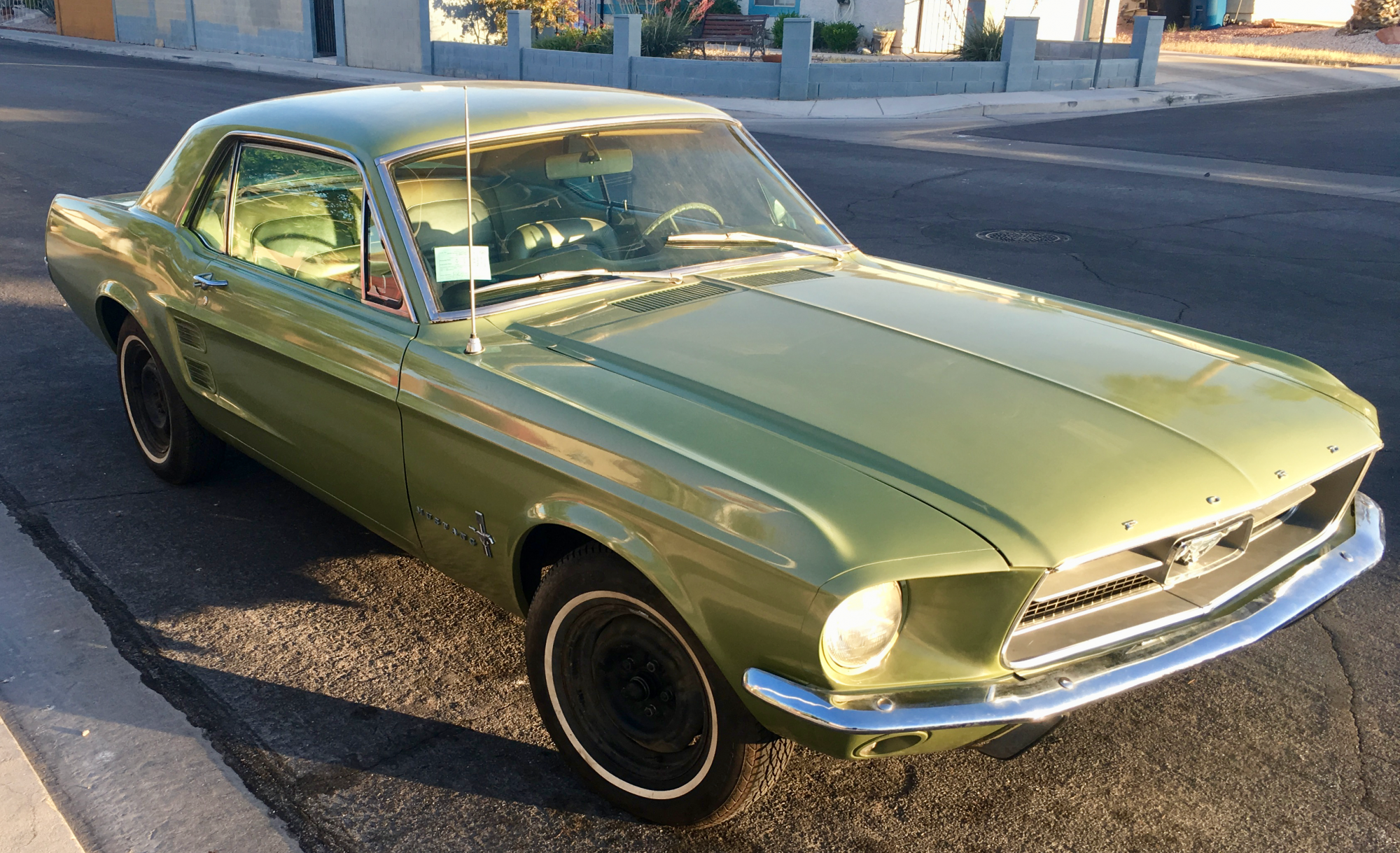
As the onion of the suspension keeps getting pealed back a usual amount of unexpected issues crop up. I’d hoped a long day, 10-11 hours would get it all sorted. Seized parts, as expected in a car this age and stubborn disassemblies add to the time.
Let’s have a look-see and what’s on deck…
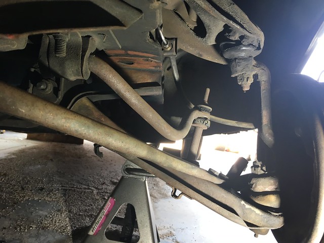
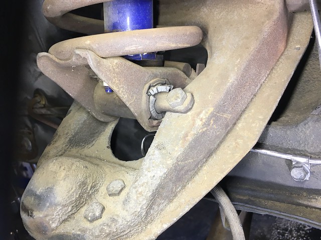
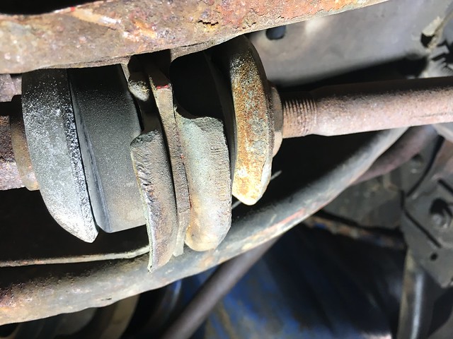
I started on the strut rods. The procedure in the book calls for removing it at the lower control arm first. Seeing the rust encrusted threads on the forward bushing bolts I went to plan B leaving it attached to the arm so it didn’t spin when I tried to remove the bolt. I hammered it with a 1/2″ impact with 700 ft/lbs breakaway torque. The nut laughed at the wrench. I used a 1/2″ breaker bar with tubing to give it a 36″ length. It took all my 265 285 lbs to get it to budge. For a one off job I’d normally go to HF and get something but they don’t have a 36″ long 1/2″ breaker bar and the truck wants a couple hundred bucks.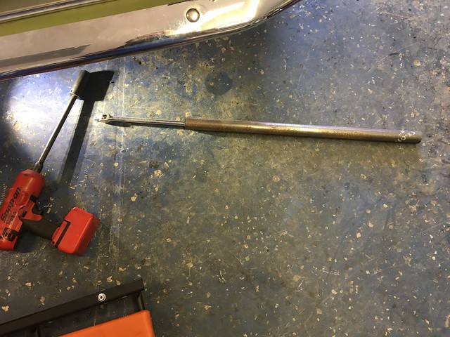
I’m thinking at one point the strut rod bushings were replaced. They don’t look at all like the FSM or the assembly manual but it’s hard to tell detail in those diagrams. And I’ve got an original printing of the first edition/run of the 67 shop manual. The replacement Drakes I got from NPD (I took the suggestions at VMF to heart and went all rubber on all the bushings) look like the drawings in both books. I haven’t done a parts history to see what the rev differences were between them. It may be that there is a rev A part on the car and that part is up to E or F. The important note being you can update the parts to current revs but not always backdate. Or so the parts manual says…
Pulled from the car.
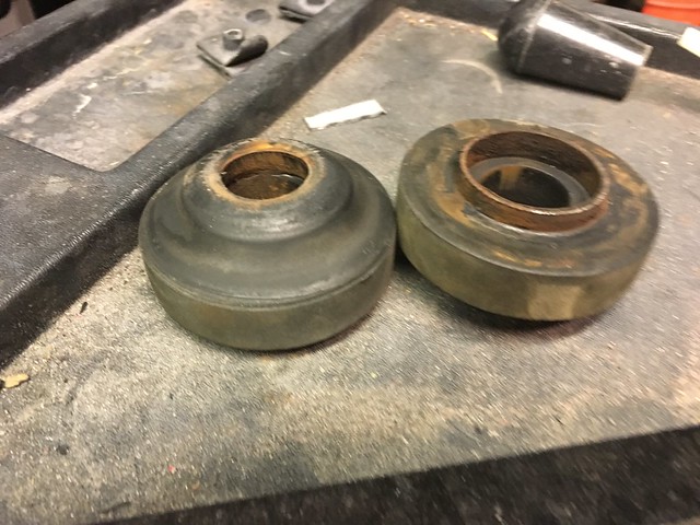
What the dudes/dudettes in Ventura sent. It’s blurry as hell but you get the gist.
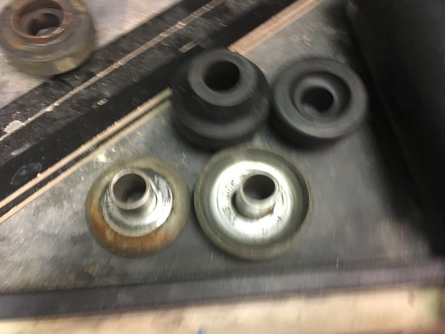
At least there is compliance and a good test fit. The old ones were like hockey pucks. The hardware and shafts are in good shape and fit to refurb.
Getting the springs out is the next step. I usually support the lower control arm with a good jack, unbolt what I need to then slowly lower the jack so the spring gently eases tension. Except the Mustang at full droop still needs an inch or two of compression to get the spring out.
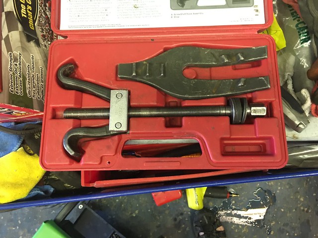
My spring compressors stripped out long ago and I’ve been using the jack method on what coil spring suspensions I’ve had. A good deal of the race stuff are coil overs. Off to Autozone to borrow one. They’ve got two kinds a conventional strut type and a through spring type. The through kind is an OEM 27035. Not exactly like the Rotunda tool from the FSM (still returns a valid part number) or even close to the Rotunda tool. And that one is way less hammered than the strut type external tool they have.
The tool. About $50 from the usual suspects. This is a loaner.
Cool original factory color dabs.
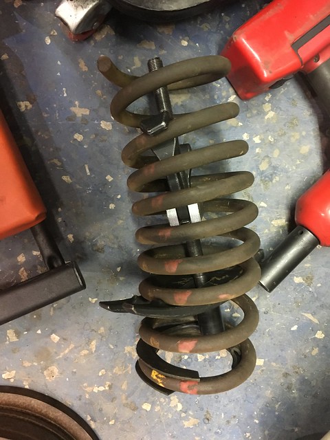
It works but with a great amount of effort. On a GM the tool is meant to go up through the spring but because of that wonderful roller perch you have to use the tool “upside down”. Which doesn’t really make a difference as long as you can get to both extremes of the spring. If you can’t the screw is too long and will hit the perch. To do this I had to remove the spring bucket support, that three sided panel that looks like it’s a glorified bump stop holder. Based on the location and construction I’d choose not to ride without that installed.
With that out you can put the swing clamps on the coil and as far as you can up the spring you install the fork that the spring is tensioned against. If you owned the tool you could shorten the threaded shaft but that would hose you for any car with a normal non vintage Mustang suspension.
There are some posts at VMF that show you how to brew your own tool that works as well as the factory tool. In my case it was late afternoon, early evening on a Friday in Vegas. I needed to get this done. Before I refinish the front clip in the fall I’ll have a go at making a tool. Right now I just need to make sure the car will handle above 40-45 mph.
A cracking of the ball joints off and we’ll be ready to go. Except these are stubborn. I have new boots all the way around so I’m not concerned with pickle fork damage to the boots. I use an air hammer fork. The tie rod came off with two hits. My forks for both the air hammer and the human hammer weren’t big enough to fully separate them. I tried the whack the upright trick from VMF and that wasn’t working. I decided with the spring out to remove the upper ball joint, then the lower control arm and take the entire assembly to the bench and beat on it over there. Using the anvil part of the vise to apply more shock to the part than just hanging from the suspension worked after several hits per joint.
Lower arm off before removing entire assembly.
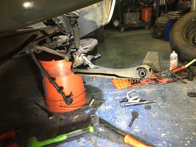
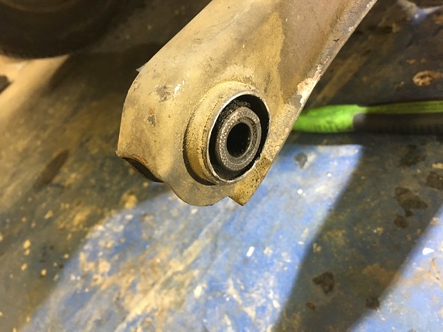
This is the “good” side of the lower arm bushing.
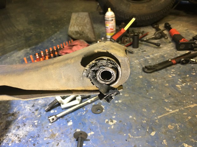
This is the “less good” side. That is correct, almost all the rubber is missing from that side. Until about half way through the bushing.
Just before I started removing parts I had a view of the car I hadn’t noticed. Usually I’m looking at it fairly close or if it’s from a distance admiring the body lines. As the car was parked on the driveway from inside the garage I got a look at camber angles that I hadn’t noticed before. The drive slopes down toward the street so my angle was if I was looking at the front on an inspection ramp. It looked like it had asymmetrical camber. Like we did in circle track. Except this was backwards as if we were going to run the track clockwise. (circle track runs counter clockwise)
I pushed on the suspension to try and settle it, turned the wheel a few times and I’ll be damned it was still there. I decided to measure it. It’s easy, a piece of square tubing and a digital angle gauge and you’re there. I indeed had -4* on one side, +3* on the other. Nowhere close to right. It could have shifted as I’ve been driving or perhaps I just didn’t notice. I can’t tell how it tracks due to all the slop in the steering. I crawled under and noticed the cam bolts on each side seemed to be in the right place for normal, symmetric camber. Ride height looked good though didn’t measure.
On the race cars we would put the car on a scale and see what the weight differences were. What’s happening here is a symptom of bent or grossly adjusted parts. Fast forward to earlier today when I finally got the lower arm detached from the upright. It’s bent. Looks like a good 1/8″ – 1/4″ plus center of bolt out of parallel from a 0 toe. That seems to have been caused by bushing wear and not hitting something. The bushing wear seemed to be causing at least an inch of for-aft movement. The other side had front impact damage at one time. I haven’t gotten there yet. There will be more surprises.
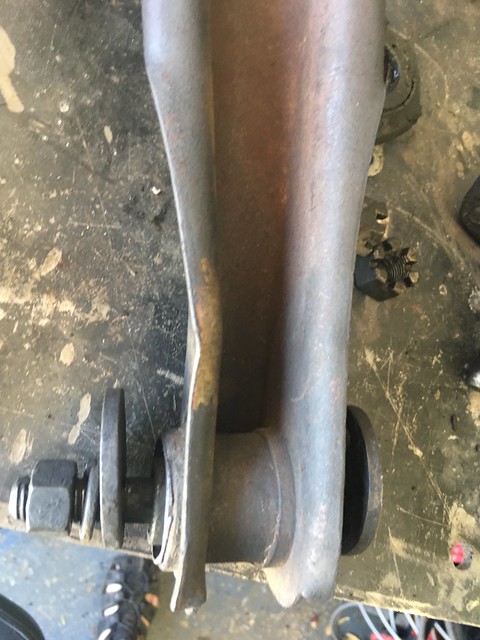
With that I needed to get that bushing out. I improvised some tooling with round tubing and plate but only got about 1/8″ or so out before there was too much strain on the rest of the part. This is where some of the others will try and spend my money. “Just get a new one, buy the Open Tracker Kit, put a better, more modern clip on it”. Good, better and more modern? Like an 83 Monte Carlo? DOH!!
The rubber was so trashed easily pressed it out with the snout of the press. My trusty 12 ton HF press in HF old school orange. When everything in HF had that oil smell from the packaging from the container ship. Rather than spend more time tooling to press the shells out (my Moog bushing have new shells) I decided to call my friend from a few posts ago Mr cut off wheel and his buddy Mr Sawsall. I made up the process as I went along. Like many other things in fabrication.
I try to take as much structural integrity out of the part I want to remove. I started with four corner cuts and a mid cut from what I’d been able to press from the arm.
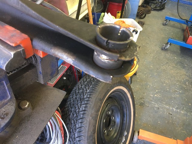
I whacked with the BFH, 5 lb sledge. No go. Out comes the Sawsall (it’s actually a Dewalt so not technically a Sawsall) We’ll clamp the part to the table and gingerly cut across the bottom. That should give us enough flex for it to come out.
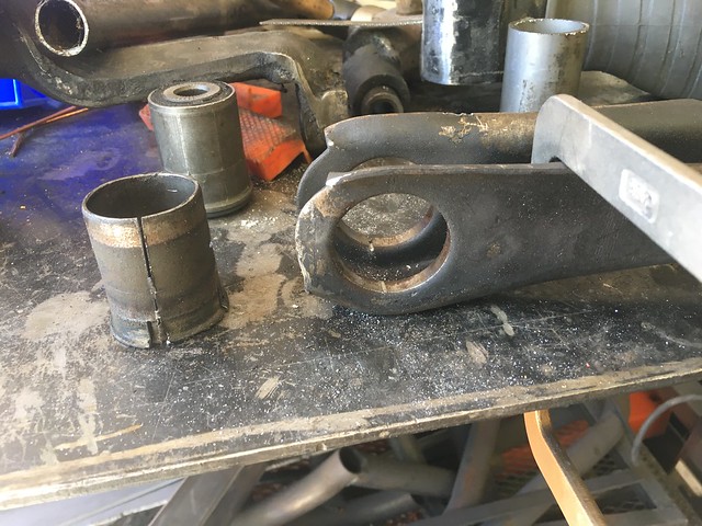
There will be a couple of nicks to TIG over and clean but all in all it was a success. Still got to get it back together.
