Car runs pretty well but has a bit of valve noise. Seems to be on #1 intake checking by ear and with a stethoscope. There is play between the push rod and lifter. Pulled the rod out and buffed it off to give it the roll test. Passed the roll test fine. Did the exercise of the top of the lifter, seems to hold pressure now. Fired it back up and no lifter noise. Throttle tested and the lifter tick came back. I really didn’t want to go into the bottom end. We’ll back burner that for now.
The throttle linkage assembly is pretty well worn. When I got in the driver’s seat to give a few revs and imagine what it’s going to be like cruising down the road as soon as I finish I noticed there wasn’t enough pedal travel to rev the engine fully.
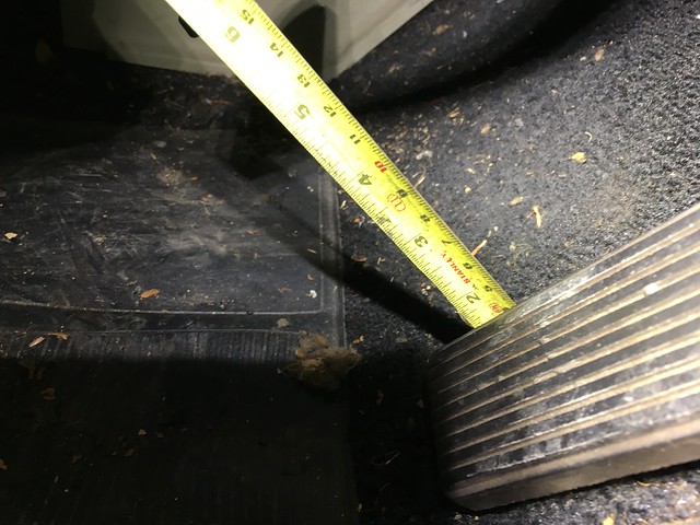
It’s supposed to spec at 4″-4-1/2″. This, well, is not. It’s pretty 50 plus years of rust. The reason the idle was so high was the linkage wasn’t returning flush against the dashpot. When returned to the proper off throttle position it more or less purrs. Particularly after 11 years on blocks. With a valve tick in #1.
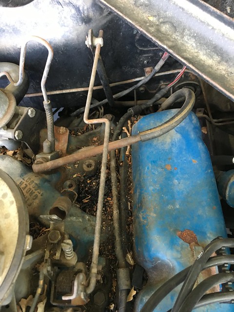
Another peeling of the onion. I can restore the accelerator links, just need some of the grommets, springs and washers. Kickdown too. I’ll take all the metal parts down to bare metal and power coat them. The black is easy enough for the pedal link but I’m still trying to decide something for the linkage rod. Perhaps a natural type metal color. Dashpot needs a spring so I’ll start trolling around here to see what my options are. Between our local industrial hardware/machine shop supply joint McFadden-Dale and McMaster-Carr I can just about get any kind of spring (or other hardware) I need. Would be nice to get “the one” for the dashpot. Checked Champion, they don’t have it. Or CJ or NPD. Or one of them had it and I couldn’t find it. Regardless, the throttle linkage project will be easy.
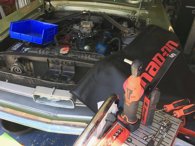
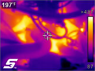
While it was running I got some heat images. The device isn’t a contact thermometer but rather a thermal imager. It measures radiated heat fields rather than specific temps. This takes into account the ambient temp as well. So when it’s 100* outside, like when I took these images, that’s factored into the image. The benefit of the tool is to read the difference in heat signatures on different parts of the engine rather than getting a specific temp reading. Because the imager averages the heat field if you need more precise temps of parts you’ll still need an IR thermometer. This is the front of the engine. There were some overheating issues prior to the car being parked. That lead to a 3 row radiator being installed. From running for 10 mins with these images it looks as expected. It’s something I’ll need to keep and eye on once I get the car back on the road.
Once the tank pickup/sender and linkage parts get here I’ll be ready to put the tank back in and go for a road test. Hopefully I’ll see them in the next couple of days.